Building a GBS Control
I decided to build a gbs-control so I can connect my PlayStation 2 over component to my LCD monitor. I have been using a generic passive convertor for component to HDMI. However my monitor doesn’t display 240p signals. Also it uses line doubling for 480i signals which causes a bobbing effect, and occasionally results in image retention. This could potentially cause long term damage. I have watched a few videos about the gbs-control project and it seems like a cost effective solution to my problem while also being a fun project.
There is a lot of information out there regarding how to build a gbs-control, so I won’t go over every step here. The goal of this page is to document my experience with the build and to note any problems I encountered. Hopefully someone my find this useful.
Parts list
Not including the wires and tools required to do the mod, I purchased the following parts.
| Part | Amount | Supplier |
|---|---|---|
| GBS8200 | 1 | Amazon Japan |
| WeMos D1 Mini NodeMcu ESP8266 | 1 | Amazon Japan |
| SI5351 Clock Signal Generator | 1 | Amazon Japan |
| 10μF 10 V 0805 (2012) ceramic capacitor | 1 | Akizuki Denshi |
| 10μF 6.3V 0603 (1608) ceramic capacitor | 3 | Akizuki Denshi |
I would have preferred to avoid purchasing from Amazon, however Aliexpress is not an option for me and I couldn’t find local suppliers for those parts. I chose to buy the capacitors from Akizuki Denshi as they had a good selection and reasonable shipping costs.
Loading GBS-Control software to the ESP8266
Following the instructions on the wiki was straight forward. I chose to “LOLIN(WEMOS) D1 R2 & mini” as my board model and that ended up working for me. However there was an error when uploading the sketch to the ESP8266 module
pyserial or esptool directories not found next to this upload.py tool.
An error occurred while uploading the sketch
Turning to the internet, I was able to find out that this is caused by the pyserial library not being fully compatible with MacOS from Big Sur onwards due to a change in how libraries need to be loaded. Luckily a quick fix, if only a hack, is available.
- Open
~/Library/Arduino15/packages/esp8266/hardware/esp8266/2.7.4/tools/pyserial/serial/tools/list_ports_osx.py - Comment lines 29 and 30, as shown below
#iokit = ctypes.cdll.LoadLibrary(ctypes.util.find_library('IOKit'))
#cf = ctypes.cdll.LoadLibrary(ctypes.util.find_library('CoreFoundation'))
iokit = ctypes.cdll.LoadLibrary('/System/Library/Frameworks/IOKit.framework/IOKit')
cf = ctypes.cdll.LoadLibrary('/System/Library/Frameworks/CoreFoundation.framework/CoreFoundation')
After that I was able to get the software compiled and uploaded to the esp8266. Supplying power by USB I was able to see the module on my wifi network, connect, and confirm that at least the web server was working as expected. All good so far.
Modding the GBS8200
For my use case, I am only interested in component input and VGA output. So I won’t be talking about mods related to HDMI or RGB at this time.
Before beginning work on the mod, I reviewed the gbs-control wiki and video guides by Voultar, RetroRGB, and Long Island Retro Gaming as guidance.
Installing the ESP8266 module
This is the essential part of the mod.
After Watching Voultar’s video I decided to mount the ESP8622 side ways prevent interference between the TrueView chip and the WiFI module. This turned out to make the installation harder than it could have been. The module I used was significantly shorter than Voultar’s, and the pin locations don’t match as nicely with the GBS8200 either.
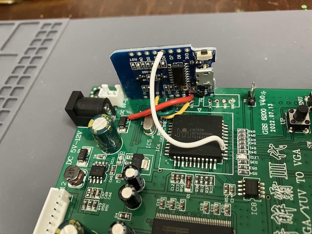
As shown in the image, the 5v pin (red wire) on the ESP2622 is positioned directly above SDL (yellow wire). It is just cramped in general. I needed to take extra care not to bridge anything between the module and the board. If I do this again I will definitely place the module elsewhere.
Stabilising the LDO
Most discussion mentions this mod is for the GBS8220 & GBS8200(2017 or yellow button) boards, but the wiki recommends it for all version. The first part, removing the capacitor at C11, was easy and the wiki states that should be enough. It also mentions that C11 could be replaced with 22uF capacitor. I decide to just remove C11 for now.
Power Supply Bypass capacitors
This part was a little frustrating as I found the wiki a little vague. To be fair I was not familiar capacitors, however I found an image in the Shumps forum thread that that listed out which capacitors could be used.
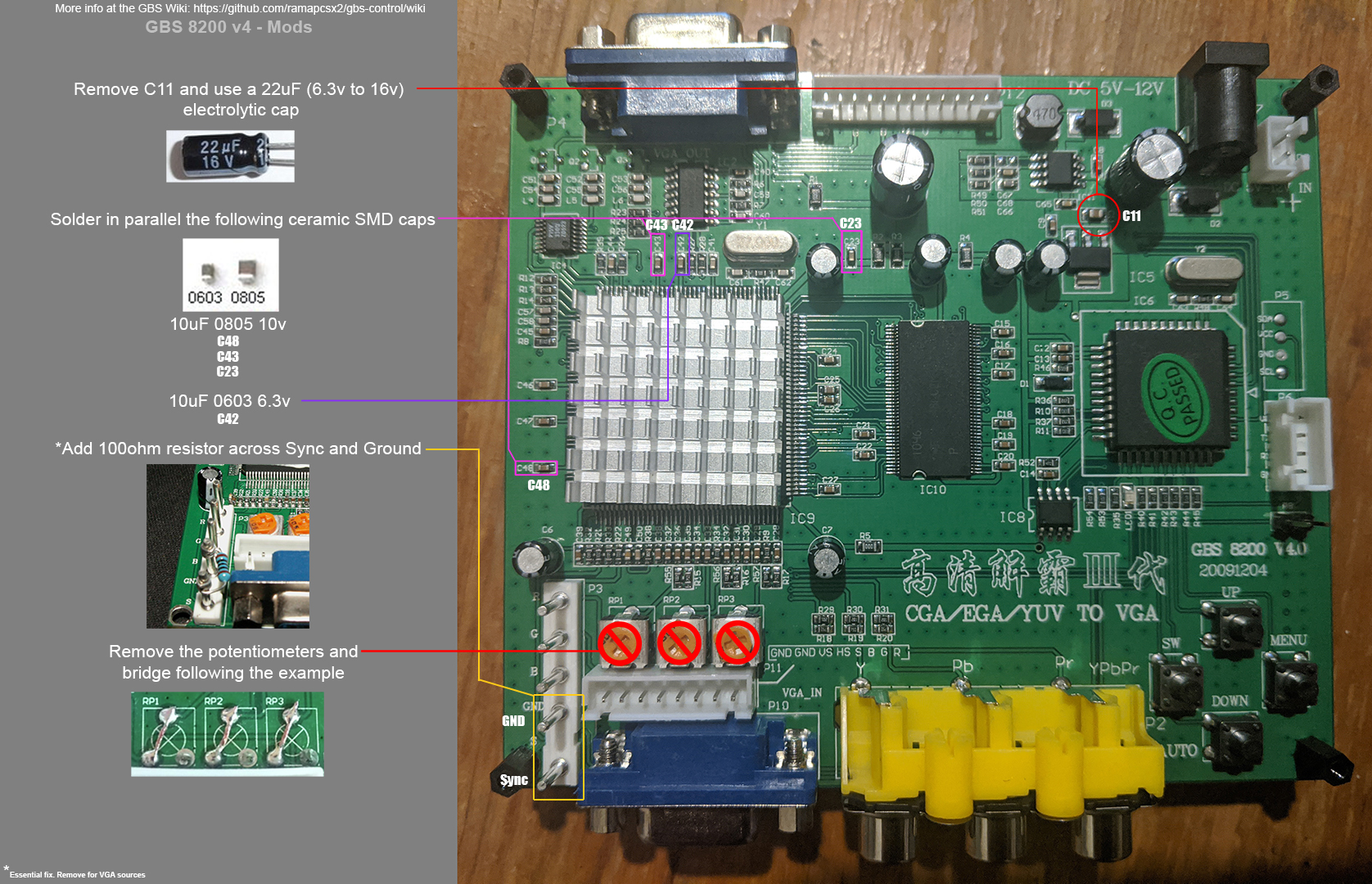
My last challenge was that my supplier, Akizuki Denshi, didn’t seem to have the capacitors in the physical sizes I was after. The reason being they listed sizes in metric; 0805 -> 2012, 0603 -> 1608.
Installing the capacitors was fiddly, but with a pair of tweezers and steady hand I managed OK. I am glad I did this before installing the clock generator.
Installing the clock generator
I am going to be upfront, I found this the trickiest part to install. The pins on the TrueView chip are smaller that the Myson Controller, and soldering to the CLK pads was hard without helping hands to keep the wire in place. I also got a bit greedy when soldering power to the clock generator, over heating the ‘unlabelled capacitor’, melting its’ solder, and pushing it out of position. Luckily I had a spare clock generator. I’ll take a look at fixing that first board when I can.
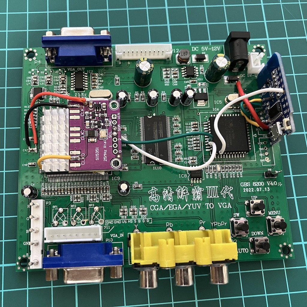
Once the clock generator was installed I connected to the web server to check that it had been detected by gbs-control. I could tell everything was ok as the option to toggle the clock generator was present in the options.
Conclusion
I am really happy I made the effort to do this. Gbs-control is a fantastic little device for the money, if you can put one together yourself. I have limited experience with soldering and did make some mistakes even when taking my time, but it was a lot more straight forward than I had expected. Having the right equipment for the job really made this easier and less stressful than past mods I have done. Also YouTube guides on soldering techniques really helped too.
As for the finished product, I love it. It has handled all the signals I have thrown at it. 240p games just work, no need for GSM. Motion Adaptive Deinterlacing is the best as I not longer need to worry about image retention or the image bobbing about. The web interface is very slick and easier to navigate than some built in upscaler menus I have used in the past. On the other hand, connecting to the web server has been iffy sometimes. I guess that is due to positioning, so I’ll be keeping an eye on that as I move forward.
A+++, would mod again.